The Troubleshooting by using Vf1-voltage
Toyota Reference TA046-TA047
Subject:
Vf
voltage information for oxygen sensor testing on 1983 and later TCCS Toyota EFI
engines.
Contributing
Source: Toyota
service manuals (a 1997).
While
in the normal diagnostic mode with T/TE1 connected to E1, the Vf voltage (feedback
voltage) switches between 0 volt and 5 volts as the 02 sensor voltage varies
between 0 volt and 1 volt.
When
testing at the Vf terminal, be sure the engine is fully warm and hold the
engine rpm 2500 to keep the IDL contacts open. Then watch the voltage. The Vf
voltage should fluctuate at least eight times every 10 seconds.
When Vf is measured at closed
throttle while the idle contacts are closed and TE and E are jumpered, the
operation of the terminal voltage changes to two steady voltages, which
indicate the following:
5v Normal (no trouble codes stored)
Ov Memory codes (trouble codes stored)
While the ECM is controlling the fuel injector duration with input or feedback from the oxygen sensor, the ECM also is learning about the amount of fuel correction that it is making. This learned value is used by the ECM during both open- and closed-loop operations to help fine tune the fuel control for each particular engine and its operating conditions.
The Vf voltage should be measured only during closed-loop feedback
operation,
such as during warm engine idle or during steady cruising. During modes of
operation such as cold engine start, acceleration, or deceleration, the Vf
voltage will often indicate 0 volt and does not reflect the learned value
stored in the ECM.
Also, if Vf is measured when the vehicle has been operating at or above 5000
feet elevation, you may see 0 volt. This is considered normal. Vf learned
value has a 20-percent effect on the air-fuel ratio.
Check Vf learned value with DVOM at Vf (or Vf1) and E1 terminals. The engine should be fully warm, and the Vf voltage (02 sensor) should have been checked for correct values.
Calculation of Basic Injection Duration
When
the fuel control process is started in the ECM, the first thing that the ECM
does is to calculate the basic injection duration. The ECM will use the sensor
information and engine data (such as volumetric efficiency) to arrive at this
number:
Vs/PIM
+ Ne + THW + THA + Engine Data = Basic Fuel Injection Duration
The
basic injector value is like the ECM's educated
guess about what the injector pulse width should be at that given time, (figure).
The basic injection value is very accurate, with ±20 percent of what the
actual value should be.
![]()
Depending
on a number of factors, including altitude, engine wear, fuel, and engine
tolerances,
the amount of correction caused by the 02 sensor feedback varies. If the amount
of correction that the ECM has to make is relatively small, such as 3 percent,
the ECM can easily accommodate it, figure.
 However, the ECM in
feedback operation is programmed to make changes in the fuel injection duration
only in small steps or increments. Thus, if operating at high altitude, the ECM
would have to make a relatively large percentage change to the basic injection
value to compensate for the lack of oxygen in the air. Thus, the ECM response
would be very slow and performance would be affected.
To avoid this situation the ECM memorizes the amount of feedback correction it
is making (like an average) over a period of time. This amount is then used in
the initial basic injection value calculation to improve its accuracy. By
making the basic injection value more accurate, the ECM will only have to make
small incremental changes (±3 percent) to the basic injection value and still
have the air-fuel ratio at the optimum value.
Diagnosis
Using Vf (TE1 Open)
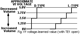
When in the diagnostic mode (TE1 grounded), voltage at the Vf terminal should move from 0 volt to 5 volts to indicate that the feedback system operating and the ECM is continually fine tuning the injector pulse width to keep the air-fuel ratio centered at about 14.65:1 The Vf voltage when TE is open tells you how much correction has been necessary to the basic injection duration to maintain that air-fuel ratio. It will range from volt to 5 volts, with the number of steps depending on the type of airflow metering used (figure).
D-type fuel injection systems (which have a pressure sensor instead of an airflow sensor) use only 3 voltage steps: 0 volt, 2.5 volts, and 5.0 volts. The 2.5-volt normal voltage covers rich or lean fuel correction of up to 10 percent. A 0-volt or 5-volt reading has the same meaning as it does on L-type injection systems.
The Vf terminal provides information on the amount of correction the ECM is making while the engine is operating (table). The ECM compares the amount it is correcting the air-fuel ratio to a set of programmed values. If the amount of correction is within its normal range, the ECM puts about 2.5 volts onto the Vf terminal.
|
Table.
Interpreting learned value |
||
|
Vf1
Signal |
Engine
Condition |
Fuel
Trim (ECM Compensation) |
|
~
0 V |
Rich |
Go
leaner -
11-20 % |
|
~
1.25 V |
Slight
Rich |
Go
leaner - 4-10
% |
|
~
2.5
V |
Normal |
Lean/rich
± (0-3) % |
|
~
3.75 V |
Slight
Lean |
Go
richer + (4-10) % |
|
~
5 V |
Lean |
Go
richer + (11-20) % |
|
D-type 2.5V |
Normal |
Lean/rich
± 10 % |
If the ECM is decreasing the amount of fuel that it thinks should be normally used, it will output a lower voltage (either 1.25 volts or 0 volt) on the Vf terminal. This will happen when the ECM is compensating for a rich condition.
|
|
If the ECM is increasing the amount of fuel that it thinks should be normally used, it will output a higher voltage (either 3.75 or 5 volts) on the Vf terminal. This will happen when the ECM is compensating for a lean condition.
In general, a 0-volt or 5-volt reading indicates a problem. The 1.25 volts or 3.75 volts is considered normal with 2.5 volts considered optimal. (When Vf voltage is at 2.5 volts, the basic injection duration needs to be adjusted by only ±3%). But if you encounter a driveability problem that sets no codes, this information can help direct you to possible problems.
If there is a lean condition that needs to be corrected, such as a vacuum leak, the ECM will add fuel to the base injection duration so that the air-fuel ratio will be at 14.65:1. If it has to increase the duration by 3 to 10 percent, the Vf voltage will be 3.75 volts. If the increase in fuel is greater than 10 percent Vf voltage will be 5.0 volts.
If
there is a rich condition that needs to be corrected, such as when the vehicle
is driven at high altitudes, the ECM will decrease fuel from the base injection
duration so that the air-fuel ratio will beat 14.65:1. If it has to correct the
duration by subtracting 3 to 10 percent, the Vf voltage will be 1.25 volts If
the decrease in fuel is greater than 10 percent, Vf voltage will be 0 volt.
Each time the ECM is disconnected or the EFI fuse is removed, the ECM will also lose its learned value stored in memory. For the ECM to relearn the value, the vehicle must be driven in closed-loop, feedback operation for a certain amount of time. The amount of time will vary depending on the engine and the type of conditions the vehicle is driven in.
If memory is lost for D-type systems, it may take up to 20 minutes for strategy to be re-learned, depending upon altitude. Airflow meter types are able to relearn faster.
Default voltage for all TCCS systems is 2.5 volts (±0 25 volt). In other words, if memory is lost, the ECM operates from an internally fixed (default) voltage.
Vf learned-value voltage measurements may not be exactly 0 volt, 1.25 volts, 2.5 volts 3.75 volts, and 5 volts and can vary by about 0.25 volt, depending on the accuracy of a voltmeter. However, the number of voltage steps (either 3 or 5) will always be the same.
Hope this is useful
Íекоторые цитаты из описания Vf1, чтобы посетители могли ознакомиться с цитатами из первоисточников. а не "пересказами" "знатока" и его слишком вольными интерпретациями.
В wwwboards.auto.ru/toyota/427324.html и wwwboards.auto.ru/toyota/428190.html несколько доступнее :-)
Íîâàÿ ïðîãðàììà äëÿ ýòèõ ñòàðûõ àâòîìîáèëåé (Read Data Stream by Vf1)
|
|
1999

 Ïоиск (Search on Site)