Read Trouble Codes A/T and SRS TOYOTA
|
Эти материалы не является
инструкцией по проведению диагностики,
а только дают представление о
методиках считывания кодов и
назначении некоторых контактов
применяемых диагностических разъемом. |
Считывание
кодов самодиагностики автоматических
коробок передач
(Reading DTC A/T)
ECT ECU monitors transaxle operation and contains a self-diagnostic system which stores trouble codes if transaxle electronic control system failure or problem exists. If a problem exists in No. 1 or No. 2 solenoids or speed sensors and trouble code is set, ECT ECU blinks OD OFF light on instrument panel to warn driver.
OD OFF light will not blink to warn driver if a problem exists or trouble code is stored for lock-up solenoid, or problem exists with brake light switch or throttle position sensor signal.
1) Turn ignition on. DO NOT start engine. Depress OD switch to the ON position.
NOTE: Trouble codes can only be retrieved with OD switch in the ON position. If OD switch is in OFF position, OD OFF light will be on continuously and will not blink the trouble code.
2) Install jumper wire between terminals TE1 and E1 of data link connector.
3) Note number of flashes from OD OFF light on instrument panel. If normal system operation exists, OD OFF light will blink 2 times per
second.
NOTE:
a) In Pickup & 4Runner need connect terminal G to Ground.
b) A stuck solenoid will not set a trouble code. Trouble codes are only set for circuit malfunctions, not mechanical failures.
4) If system is operating correctly (normally) and no trouble code exists, turn ignition off and remove the jumper wire. Perform the MANUAL SHIFTING TEST under TRANSMISSION SHIFT TESTING to determine if problem is electrical or mechanical. Check system by the symptom.
5) If trouble code exists, OD OFF light will flash once every second. The number of flashes will equal first digit of trouble code. After a pause of 1.5 seconds, second digit will be displayed.
6) If more than one trouble code exists, next trouble code will be displayed after pause of 2.5 seconds. Smallest value trouble code will be first. Trouble codes will be repeated.
7) Once trouble code is obtained, determine probable cause and symptom.
Turn ignition off and remove jumper wire.
NOTE: Once repairs have been performed, trouble codes must be cleared from ECT ECU memory.
Reading Diagnostic Codes (Cressida & Supra W/Super Monitor Display)
CAUTION: DO NOT depress accelerator pedal while checking codes with Super Monitor Display. Depressing of accelerator pedal will cancel the display.
1) Turn ignition on with engine off. Simultaneously push and hold the SELECT and INPUT M keys for at least 3 seconds.
2) After a short time, hold the SET key for at least 3 seconds. If system is operating correctly, ECT OK will appear on the screen. If a malfunction exists, the code number will be displayed on the screen.
3) If 2 or more codes are stored, a 5 second pause will occur between the codes. If codes are stored, note code number and repair appropriate circuit. See appropriate DIAGNOSTIC CODES table. It diagnostic codes 62, 63, 64 or 65 occur, an electrical failure in she solenoids is indicated. Mechanical failures such as sticking switches will not appear as diagnostic codes.
4) Once diagnostic code is confirmed, turn ignition off or push DISPLAY key to obtain time reading on the screen.
DIAGNOSTIC CODES (EXCEPT A-341E) TABLE
42 Defective No. 1 speed sensor- Severed wire harness or short circuit. Fault ECU.
44 Defective rear wheel speed sensor (in transfer left case). Severed wire harness or short circuit.
61 Defective No. 2 speed sensor. Severed wire harness or short circuit. Faulty ECU.
62 Defective No. 1 solenoid. Severed wire harness or short circuit. Faulty ECU.
63 Defective No. 2 solenoid. Severed wire harness or short circuit. Faulty ECU.
64 Defective lock-up solenoid. Severed wire harness or short circuit.
65 Defective No. 4 solenoid. Severed wire harness or short circuit.
DIAGNOSTIC CODES (A-341E) TABLE
42 The No. 2 speed sensor signal is input, but No. 1 speed sensor signal is not input while vehicle is being driven in a shift range other than the N range.
46 Current does not flow to the No. 4 solenoid circuit for a set period of time or longer when the ECU output duty ratio to the No. 4 solenoid is 90% or higher.
61 The No.1 speed sensor signal is input, but No. 2 speed sensor signal is not input while vehicle is being driven in a shift range other than the N range.
62, 63 Solenoid resistance is 8 ohms or lower when solenoid is energized. Solenoid resistance is 100k ohms or higher when solenoid is not energized.
64 Current does not flow to the No. 3 solenoid circuit for a set period of time or longer when the ECU output duty ratio to the No. 3 solenoid is 90% or higher.
67 When NO signal (output shaft RPM) is above 1000 RPM. NCO signal (input shaft RPM) is below 500 RPM.
68 The kickdown switch is turned on before the accelerator pedal starts pushing in the switch.
CANCELING
DIAGNOSTIC CODES (ALL MODELS)
1)
After repairing the electrical fault all diagnostic codes must be cleared
from the ECU. Cancel the codes by removing the correct fuse for 10 seconds
or more with the engine OFF See FUSE APPLICATION table. Fuse may have to be
removed for longer period of time depending on ambient temperature.
FUSE
APPLICATION TABLE
Application
Fuse
Block Marking Fuse Amp
Cressida
A-340A
EFI
20
Lexus
LS 400 A-341E
EFI
20
Pickup
& 4Runner:
A-340E,
A-340F & A-340H
EFI
15
Supra
A-340E
DOME
20
2)
Diagnostic codes can also be canceled by disconnecting negative battery
cable. In this case all memory systems such as the clock, radio and computer
control system will also be lost. Diagnostic codes can also be canceled by
disconnecting the ECU.
3)
If diagnostic codes are not canceled, they will be retained and appear with
other codes in the event of further malfunctions.
P-codes
. DTC P0500 - Vehicle Speed Sensor Malfunction
. DTC P0750 - Shift Solenoid "A" Malfunction
. DTC P0753 - Shift Solenoid "A" Electrical Malfunction
. DTC P0755 - Shift Solenoid "B" Malfunction
. DTC P0758 - Shift Solenoid "B" Electrical Malfunction
. DTC P0770 - Shift Solenoid "E" (SL) Malfunction
. DTC P0773 - Shift Solenoid "E" (SL) Electrical Malfunction
. DTC P1520 - Stop Light Switch Signal Malfunction
. DTC P1705 - Direct Clutch Speed Sensor Circuit Malfunction
. DTC P1765 - Shift Solenoid Valve SLN Circuit Malfunction
. DTC P1780 - Park/Neutral Position Switch Malfunction
Note:
Not all trouble codes are used on all models
После включения зажигания необходимо перевести переключатель “
O/D” в положение “ON” и соединить контакты E1 и Te1. По количеству вспышек и периоду времени между ними определяют код ошибки.DTC A-442F опубликованы в отдельной заметке.
Следует помнить, что
возможности самодиагностики не
безграничны и ECT ECU не определяет некоторые
неисправности.
«…Подключите положительный щуп DVOM (цифрового тестера) к контакту “Tt” и отрицательный к контакту “E1” и включите зажигание, но не запускайте двигатель.
Проверьте, исправность датчика положения дроссельной заслонки (TPS или Throttle Position Sensor) и исправность его электрической цепи, контролируя напряжение при перемещении дроссельной заслонки, т.е. при постепенном нажатии на педаль газа. Напряжение должно увеличивать плавно (без т.н. «дребезга контакта») в диапазоне от 0 до 8 В. Напряжение датчика педали тормоза может быть проверено при полностью нажатой педали газа, т.е. при положении TPS-датчика в положении WOT (wide open throttle) и нажатии на педаль тормоза. Когда педаль тормоза нажата, тестер должен показывать 0 В. Когда педаль отпущена, напряжение должно быть 8 В.
Сигнал переключения режимов A/T может быть проверен при движении со скоростью не менее 10 км/час с включенным O/D при прогретом двигателе. Напряжение должно быть в диапазонах (см. таблицу) соответствующих режиму A/T. Режим A/T может определяться по толчкам свойственным процессу переключения или по оборотам двигателя и скорости движения автомобиля. Если напряжение не соответствует указанным для TPS, датчика педали тормоза или для сигналов управления режимами коробки, проверьте цепи электрического управления. Если все тесты проходят нормально т.е. неисправность не выявлена, проведите механические тест
|
|
|
"Tt" terminal voltage |
Gear position |
|
|
Below 0.5 v |
1st |
|
|
1.5 ~ 2.6 v |
2nd |
|
|
2.5 ~ 3.6 v |
2nd lockup |
|
|
3.5 ~ 4.6 v |
3rd |
|
|
4.5 ~ 5.6 v |
3rd lockup |
|
|
5.5 ~ 6.6 v |
O/D
|
|
|
6.5 ~ 7.6 v |
O/D lockup…] |
Read & Clear DTC of SRS (AirBag System)
DTC Check.
Present Troubles Codes.
1) Turn the ignition switch to ACC or ON position and wait approx. 20 seconds.
2) Using SST (or suitable wire), connect terminals Tc and E1 of the DLC No.1 or the other "type" connectors
Past Troubles Codes.
1) Using SST (or suitable wire), connect terminals Tc and E1 of the DLC No.1
2) Turn the ignition switch to ACC or ON position and wait approx. 20 seconds.
После включения
положения замка зажигания “Acc”
или “Ign”
и паузы не менее 20...30 секунд, необходимо
соединить контакты “Tc”
и “E1”. По
количеству вспышек лампы “AirBag” и длительности
пауз между ними определяют код(ы)
неисправности (Read the 2-digit DTC as indicated by the number
of times the SRS
warning light blinks). Здесь
коды ранних моделей.
Коды самодиагностики для авто выпуска
после 1997 года опубликованы.
Очистка кодов самодиагностики (Clear DTC, e.g. by "old" Engine Check
Connector)
 Примечание: Это изложение
Руководства по ремонту Toyota не
предназначено для того, чтобы быть
заменой фактических публикаций (The
original Toyota
Repair Manuals RM179U1 и RM179U2).
Рекомендуется любому владельцу получить
(приобрести) оригинал Руководства по
ремонту (RM179U1 и RM179U2) в любом региональном
Представительстве Toyota или Центре
обслуживания или в Toyota
Motor Corporation
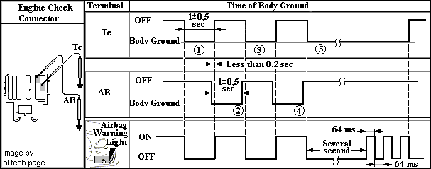
(a) Соедините контакты «Tc» и «AB» диагностического разъема с проводами соответствующей длины.
(b) Поверните замок зажигания в положение «ACC» или «IGN», сделайте паузу не менее 6 секунд.
(с) Начиная с контакта «Tc», присоедините поочередно контакты «Tc» и «AB» с корпусом («минусом») с периодом 1.0 ± 0.5 секунды дважды. После этого сохраните соединение контакта «Tc» с минусом.
Примечание: При чередовании присоединений с корпусом (кузовом) контактов «Tc» и «АВ» отсоединяйте один при уже замкнутом другом контакте. Интервал времени между замыканиями должен быть в пределах указанных на рисунке.
(d) Через нескольких секунд, когда индикатор «Airbag» "заморгает", очистка памяти кодов самодиагностики закончена.
Примечания:
** Для автомобилей, выпущенных после 1995 г.
и оборудованных диагностическими разъемами J1962
или ISO 15031-2 , тоже возможно "ручное" считывание и
стирание кодов..
SRS DTC CHECK (USING SST CHECK WIRE)
(a) Check the DTCs (Present trouble code).
(1) Turn the ignition switch to the ON position, and wait for approximately 60 seconds.
(2) Using SST (or the suitable Wire as shown in photo), connect terminals TC and CG of the DLC3.
(b) Check the DTCs (Past trouble code).
(1) Using SST, connect terminals TC and CG of the DLC3.
(2) Turn the ignition switch to the ON position, and wait for approximately 60 seconds.
NOTICE: Connect the terminals to the correct positions to avoid a malfunction.
(c) Read the DTCs.
(1) Read the blinking patterns of the DTCs.
• Normal system code indication (w/o past trouble code): the light blinks twice per second.
• Normal system code indication (w/ past trouble code): when the past trouble code is stored in the center airbag sensor assembly, the light blinks only once per second.
• Trouble code indication: the first blinking indicates the first DTC. The second blinking occurs after a 1.5-second pause.
If there are more than 1 code, there will be a 2.5-second pause between each code. After all codes are shown, there will be a 4.0-second pause, and then they all will be repeated.
HINT:
• If 2 or more malfunctions are found, the indication begins with the smaller numbered code.
• If DTCs are indicated without connecting the terminals, proceed to the "TC and CG Terminal Circuit"
DTC CLEAR (USING SST CHECK WIRE)
(a) Clear the DTCs.
(1) When the ignition switch is turned to the LOCK position, the DTCs are cleared.
HINT: Depending on the DTC, the code may not be cleared by turning to the LOCK position the ignition switch. In this case, proceed to the next procedure.
(2) Using SST, connect terminals TC and CG of the DLC3, and then turn the ignition switch to the ON position.
(3) Disconnect terminal TC of the DLC3 within 3 to 10 seconds after the DTCs are output, and check if the SRS warning light comes on after 3 seconds.
(4) Within 2 to 4 seconds after the SRS warning light comes on, connect terminals TC and CG of the DLC3.
(5) The SRS warning light should go off within 2 to 4 seconds after connecting terminals TC and CG of the DLC3. Then, disconnect terminal TC within 2 to 4 seconds after the SRS warning light goes off.
(6) The SRS warning light comes on again within 2 to 4 seconds after disconnecting terminal TC. Then, reconnect terminals TC and CG within 2 to 4 seconds after the SRS warning light comes on.
(7) Check if the SRS warning light goes off within 2 to 4 seconds after connecting terminals TC and CG of the DLC3. Also check if the normal system code is output within 1 second after the SRS warning light goes off.
If DTCs are not cleared, repeat this procedure until the codes are cleared.
Последнне время участились случаи считывания кодов неисправности
SRS
DTC B1650* (flash-code 32) = "OCCUPANT CLASSIFICATION SYSTEM Malfunction"
и его аналога
DTC
B1150.
Для некоторых Toyota есть
TSB с таким указанием. IMPORTANT SERVICE NOTE:
If system initialization is not performed after an OCS DTC is set, SRS codes B1650 or B1150 will not clear and the system may not operate properly. Be sure to perform the “Zero Point Calibration” and “Sensitivity Check Procedure” for the conditions listed below.
- The occupant classification ECU is replaced.
- Accessories (seatback tray or seat cover, etc.) are installed on the seat.
- The passenger seat is removed from the vehicle.
- Both the SRS warning light and passenger airbag (“OFF”) indicator light comes on.
- The vehicle is involved in an accident or collision.
|
|
Методика и
коды самодиагностики Suspension.
Методика считывания кодов ABS.
|
2000-2018 al tech page |



 Поиск (Search on Site)