Diagnostic specific Wide Range Oxygen Sensor aka Air / Fuel Ratio Sensor Toyota
(by Scan Tools and DVOM)
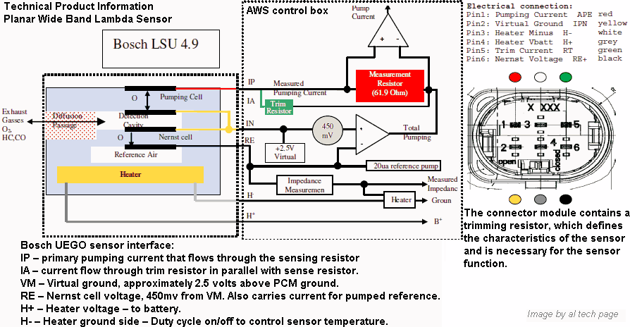
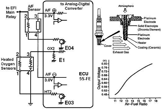
The ECM uses an Oxygen Sensor to ensure the Air/Fuel Ratio is correct for the Catalytic Converter. Based on the oxygen sensor Signal, the ECM will adjust the amount of fuel injected into the intake air stream. This style of Oxygen Sensor has been in service the longest time. It is made of zirconia (zirconium dioxide), platinum electrodes, and a heater. The oxygen sensor generates a voltage signal based on the amount of oxygen in the exhaust compared to the atmospheric oxygen. The zirconia element has one side exposed to the exhaust stream, the other side open to the atmosphere. Each side has a platinum electrode attached to Zirconium dioxide element.
Titania oxygen sensor is used on the Corolla GTS except California- and the V-6, 2WD California truck. The sensor uses a thick film of titania at the tip of the element to detect oxygen concentrations in the exhaust gas. The key difference between the titania sensor and the more common zirconia sensor used on all other models is that the zirconia element generates voltages according to the oxygen concentration in the exhaust gas.
The Air-Fuel Ratio (A/F) sensor is similar to the narrow range oxygen sensor. Though it appears similar to the oxygen sensor, it is constructed differently and has different operating characteristics. The A/F sensor is also referred to as a wide range or wide ratio sensor because of its ability to detect air/fuel ratios over a wide range. The advantage of using the A/F sensor is that the ECM can more accurately meter the fuel reducing emissions.
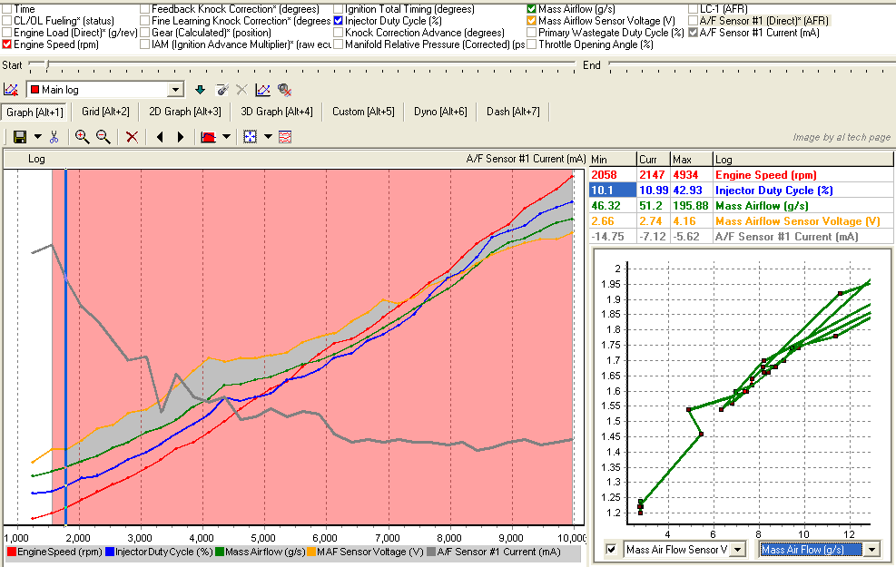
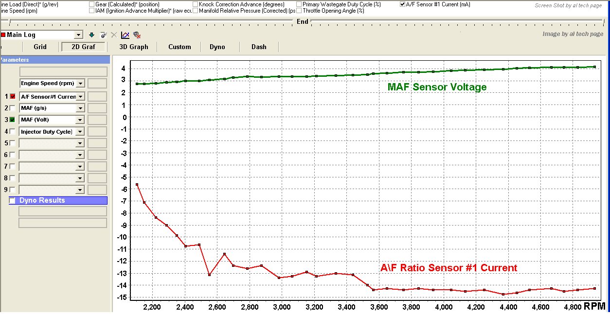
The A/F Ratio sensor Toyota (Part No. 89467-...) signal voltage varies according to the amount of oxygen sensors in the exhaust stream (see figure). Unlike the signal voltage from a heated oxygen sensors (HO2S), the A/F sensors signal voltage increases as the air-fuel mixture leans and decreases as the air-fuel mixture richens. The signal voltage ranges from 0.48 to 0.80 volts! While the vehicle runs in closed loop mode, the ECU uses the A/F sensor signal to lengthen or shorten the fuel injector pulse width until attaining a stoichiometric air-fuel mixture.
The A/F sensor contains a ECU-controlled heater. At start-up, the heater helps warm the A/F sensors to quickly operating temperature. With minimal exhaust gas flow, the heater keeps the A/F sensor from cooling down.
Take a look Photo Wide Range Air Fuel Ratio Sensors and this Articles (Russian): A/F Ratio Sensors (Description), A/F Ratio Sensors (Diagnostic)
The voltage shown on the chart is what one would see if one were using the factory Toyota scan tool to measure the A/F sensor parameter. Toyota states that the output of this sensor can only be measured with a scan tool. (It appears that the Toyota factory scan tool and the Vetronix Mastertech with the Toyota OE software are the only tools that support this parameter currently). This is not true! Besides, on Engines with these Sensors voltage that corresponds with a specific A/F ratio is above (to 4.0 Volts).
Diagnostic Trouble Codes Toyota about Oxygen / AFR Sensors (Some)
News 2010. DTC P2A00& P2A03 are Replaced with new DTC for Slow and Delayed Air-Fuel Ratio Sensor Response: P014C, P014D, P014E, P014F, P015A, P015B, P015C, P015D.
Cylinder (Air-Fuel Ratio) Imbalance DTC P219A / P219B = Bank 1 AFR Imbalance / Bank 2 AFR Imbalance.
ECM monitors the Difference in A/F Ratio between each Cylinder on Bank1 / on Bank 2.
DTC P0125 Insufficient Coolant Temp. For Closed Loop (P1154)
DTC P0171 System Too Lean (Fuel Trim)
DTC P0172 System Too Rich (Fuel Trim)
DTC P0420 Catalyst System Efficiency Below Threshold
DTC P1031, P1032, P1051, P1052, P1131, P1132, P1151, P1152, P1154
DTC P1130 A/F Sensor Circuit Range Problem
P1132 A/ F Sensor Circuit High Bank 1 Sensor 1
DTC P1133 A/F Sensor Circuit Response Malfunction
DTC P1135 A/F Sensor Heater Circuit Malfunction
DTC P1150 A/F Sensor Circuit Range Problem
DTC P1153 A/F Sensor Circuit Response Malfunction
DTC P1155 A/F Sensor Heater Circuit Malfunction
P2A00 A/F Sensor Circuit Slow Response (B1S1)
P2A03 A/F Sensor Circuit Slow Response (B2S1)
DTC P2195* Oxygen Sensor Signal Stuck Lean (Bank 1 Sensor 1) TSB-0066-10
DTC P2196* Oxygen Sensor Signal Stuck Rich (Bank 1 Sensor 1)
DTC P2197* Oxygen Sensor Signal Stuck Lean (Bank 2 Sensor 1)
DTC P2198* Oxygen Sensor Signal Stuck Rich (Bank 2 Sensor 1)
P2237* Oxygen Sensor Pumping Current Circuit / Open (for A/F sensor) (B1S1)
P2238* Have Many TSB for Recalibrate/Reflash ECM and/or Replace Both A/F Sensors
(with New OEM Part. No.) ТSB-0379-08, ТSB-0278-08)
P2239*, P2240*, P2241*
P2242* Oxygen Sensor Pumping Current Circuit / High (for A/F sensor) (B2S1)
P2251*
P2252* Oxygen Sensor Reference Ground Circuit Low (for A/F sensor) (B1S1)
P2253* Oxygen Sensor Reference Ground Circuit High (for A/F sensor) (B1S1)
P2254*, P2255*, P2256*
P3195/ P3196A/ F sensor circuit range / Performance lean side, Bank1 Sensor1 / Bank2 Sensor1
P3231 A/ F sensor plus minus circuit correlation (Bank 1 Sensor 1)
P3232 A/ F sensor plus minus circuit correlation low (Bank 1 Sensor 1)
P3233 A/ F sensor plus minus circuit correlation high (Bank 1 Sensor 1)
P3243 A/ F sensor plus circuit (Bank 1 Sensor 1)
P3245 A/ F sensor plus circuit low voltage Bank 1 Sensor 1
P3246 A/ F sensor plus circuit high voltage Bank 1 Sensor 1
P3251 A/ F sensor minus circuit Bank 1 Sensor 1
P3252 A/ F sensor minus circuit low voltage Bank 1 Sensor 1
P3253 A/ F sensor minus circuit high voltage Bank 1 Sensor 1, etc.


a) Disconnect the A/F sensor connector.
b) Using an ohmmeter measure the resistance between terminals +B and HT. Resistance: 0.8 - 1.4* ohms at 20°C (68°F). If the resistance is not as specified, replace the sensor.
Torque: 44 Nm (440 kgf.cm, 31 ft.lbf)
c) Reconnect the A/F sensor connector.
* On new Cars - to 3.4 ohms
| Parts | OEM Part No. | Old Price | |
|---|---|---|---|
| Oxygen Sensor | Front: | ||
| Federal | 89465-06030 | $140.48 | |
| California | 89467-41011 | $257.30 | |
| Rear: | |||
| Federal | 89465-33120 | $146.35 | |
| California | 89467-41021 | $257.30 |
Note. Toyota has use new "Planar" A/F Sensor. A second generation it Sensor was developed to meet more stringent emission regulations. This A/F Sensor reaches operating temperature faster that the previous (aka Cup Element) A/F sensor. This allows the ECM to go into closed loop vuel control faster when the engine is cold reducing cold start emission.
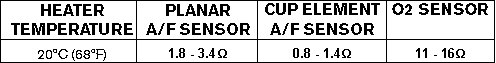
The heater resistance for the planar AF sensor is slightly higher than the cup element A/F sensor. Heater resistance is checked with a DVOM. A characteristic of this AF sensor is that when it fails it can drive the A/F signal output high or low causing a rich or lean condition.
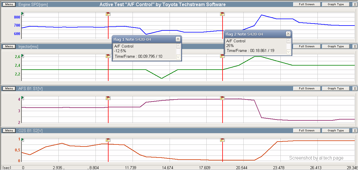
Active Test "A/F Control" by Toyota Techstream Lite
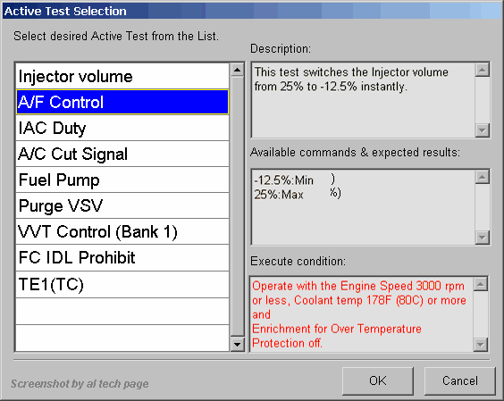
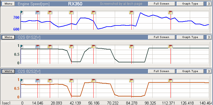
INSPECTION PROCEDURE (The Best Way).
HINT: Hand-held tester only: The narrowing down the trouble area is possible by performing ACTIVE TEST of the following ”A/F CONTROL” (oxygen sensor or another can be distinguished).
(a) Perform ACTIVE TEST by hand-held tester (A/F CONTROL). HINT: ”A/F CONTROL” is an ACTIVE TEST which changes the injection volume to -12.5 % or +25 %.
(1) Connect the hand-held tester to the DLC3 on the vehicle.
(2) Turn the ignition switch ON.
(3) Warm up the engine with the engine speed at 2,500 rpm for approx. 90 sec.
(4) Select the item ”DIAGNOSIS/ENHANCED OBD II/ACTIVE TEST/ A/F CONTROL”.
(5) Perform ”A/F CONTROL” when idle condition (press the right or left button).
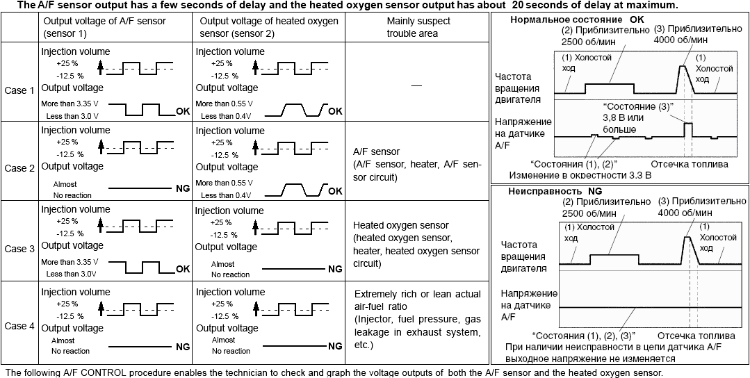
Result: Air fuel ratio sensor and oxygen sensor reacts in synchronizing with increase and decrease of injection volume (For HO2S: +25 % " rich output: to 1 V, -12.5 % " lean output: to 0 V)
For Example. 2002 Toyota Camry LE, Engine: 3.0 L / 6 cyl / Gas / DOHC, Fuel: Fuel Injection, Ignition: Distributorless, Trans: 4-speed Automatic Transaxle (Electronic) U140E, Mileage: 43,318 mi,
Emissions: OBD-II Compliant (ISO 9141-2), VIN: 4T1BF32K52 (MCV30L-CEPNKA) I read DTC (by using scantools CJ-II and Intelligent Tester II Toyota): P1130 "A/F Sensor Circuit Range/Performance Malfunction (Bank 1 Sensor 1)" and 1135 "A/F Sensor Heater Circuit Malfunction (Bank 1 Sensor 1).
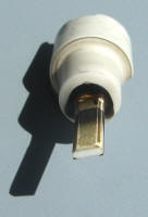
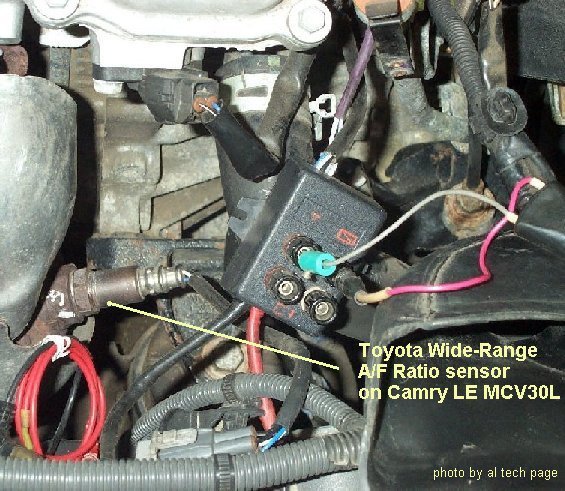
Use description for diagnostic courtesy by John Thornton I check Voltage and DC on this Sensor (photo). After installed "new" Sensor (from other, but good Camry) these codes P1130 and P1135 returned. I don't know «what to do (make) and what to check up?". After install new Sensor - all is O'k
https://www.clublexus.com/forums/rx-1st-gen-1999-2003/181807-rx300-code-p1135.html
Like previous O2 and AF Sensors, the planar AFS has ambient air on one side of the ZrO2 and exhaust gases on the other side.
The planar AFS has the same detecting range and signal characteristics as the previous cup element. But heater element has higher resistance! This AFS is not interchangeable with the older, cup element AFS. Heater Resistance (at 68 degr.F) = 1.8-3.4 Ohm. The heater is imbedded into aluminum oxide. When the heater is ON, the aluminum oxide conducts heat directly to the zirconium dioxide layer bring the AFS to operating temperature quickly.
The heater monitor continuously detects over current or under current condition and set DTC in one trip.
The never planar AFS can be identified by its shorted body (13 mm).
Take a look this the better Descriptions for Diagnostic these Sensors in Articles of Diagnostic Page.
Air Fuel Ratio Sensors Current